Difference between revisions of "Vertical component verification"
| Line 22: | Line 22: | ||
{| | {| | ||
| − | [[File:TEST_245_0_0_fwd_v_recip_ts.png|thumb| | + | | [[File:TEST_245_0_0_fwd_v_recip_ts.png|thumb|800px]] |
|} | |} | ||
Revision as of 22:01, 17 May 2024
This page documents our efforts to verify that the vertical component codes are working correctly.
Code status
The SGT codes contain provisions for calculating Z-component SGTs - the impulse is applied in the Z direction. As part of our migration from RWG to AWP for producing SGTs, we went through an extensive code comparison process, which identified that Z component SGTs must be multiplied by two when being converted from AWP to RWG format. This is, according to emails with Rob, "to account for the free-surface effect for the Z component force. In AWP-ODC I believe the Z-component is located at the free-surface whereas the X & Y components are ½ grid above/below. In my code the free-surface is coincident with the X & Y components, and Z is ½ grid above/below (I apply the factor of 2 free-surface scaling to the X & Y forces within the FD code)."
The DirectSynth and JBSim3d codes already contain provisions to pass in the vertical component SGTs and their headers and synthesize 3-component seismograms. Note that when 3-component seismograms are outputted, the 1st component in the file is the vertical component.
The CyberShake interfaces to the broadband codes needed to be modified to correctly handle the vertical component - hb_high creates a 3-component stochastic seismogram, but the low-frequency site response and merging codes had to be modified.
A number of helper scripts (extracting individual rupture variations, plotting seismograms, etc.) had to be modified to support 3-component seismograms.
Testing, round 1
For initial testing, the TEST site was run with Z-component SGTs, and post-processing and broadband calculations were run. We confirmed that the horizontal component seismograms were identical whether run by themselves or as part of 3 components, and plotted them to confirm they looked "seismic".
Testing, round 2
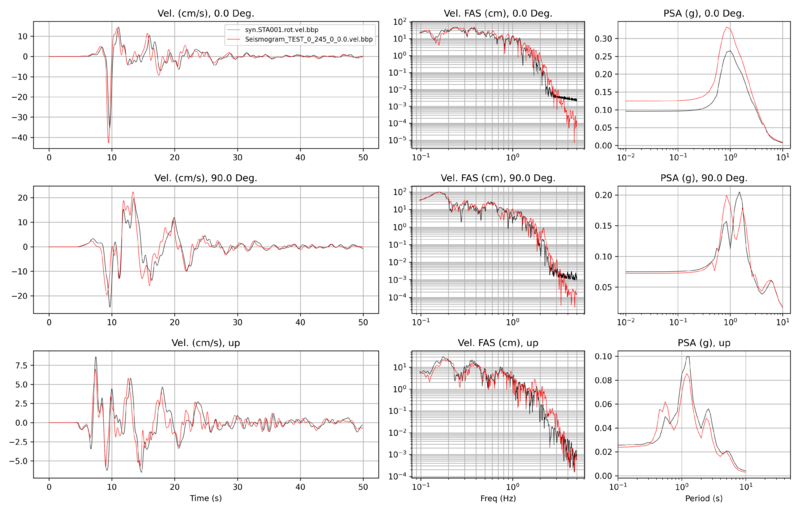
To confirm the vertical component results were correct, we attempted to replicate the reciprocity simulations in a forward simulation, for the TEST site, with a volume rotated at -55 degrees, the velocity model constructed using Study 22.12 parameters, and for source 245, rupture 0, rupture variation 0. The only difference we were aware of is that the forward simulation was performed to a depth of 48 km, whereas the reciprocity simulation was to a depth of 50 km.
Velocity seismogram comparison:
