Difference between revisions of "BBP Multi-Segment Ruptures"
| Line 118: | Line 118: | ||
Below are GOF plots produced by using a single plane versus the 3-segment rupture. | Below are GOF plots produced by using a single plane versus the 3-segment rupture. | ||
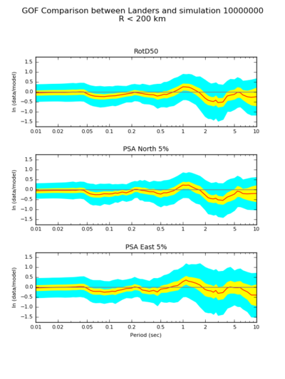
| − | [[File:Gof-Landers-234_r0-200-rd50.png| | + | [[File:Gof-Landers-10000000_r0-200-rd50.png|400px|alt=GOF Plot for Single-segment Landers|GOF Plot for Single-segment Landers]] |
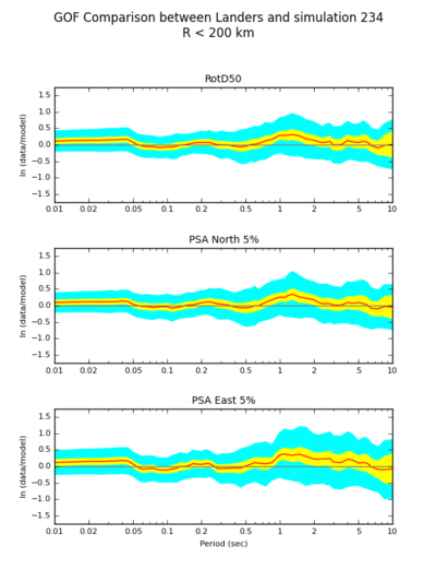
| + | [[File:Gof-Landers-234_r0-200-rd50.png|400px|alt=GOF Plot for Multi-segment Landers|GOF Plot for Multi-segment Landers]] | ||
Revision as of 21:33, 22 August 2016
This page describes the implementation of Multi-Segment Ruptures on the Broadband Platform. For the example described in this page, we use the 1992 Mw 7.2 Landers earthquake. We use 3 separate SRC files to provide rupture parameter descriptions for a 3-segment Landers rupture model. These SRC files can be run independently through the BBP, and then the resulting time series for each station summed together across the 3 segments.
SRC Description
The BBP source description file containing a single plane Landers event is show below for comparison:
#
# Landers source file
#
MAGNITUDE = 7.22
FAULT_LENGTH = 80.00
FAULT_WIDTH = 21.00
DEPTH_TO_TOP = 0.0
STRIKE = 344
RAKE = 180
DIP = 89
LAT_TOP_CENTER = 34.416
LON_TOP_CENTER = -116.505
HYPO_ALONG_STK = -25.00
HYPO_DOWN_DIP = 7.00
#
# Model specific parameters
#
DLEN = 0.1
DWID = 0.1
#
# Alternative SEEDS create alternative slip distributions
#
SEED = 2379646
For describing the 3-segment Landers earthquake, we use 3 separate SRC files, as show below:
- Segment 1
MAGNITUDE = 7.220
LAT_TOP_CENTER = 34.214577
LON_TOP_CENTER = -116.436576
DEPTH_TO_TOP = 0.0
STRIKE = 355
DIP = 90
RAKE = 180
FAULT_LENGTH = 32.0
DLEN = 0.1
FAULT_WIDTH = 20.4
DWID = 0.1
HYPO_ALONG_STK = -2
HYPO_DOWN_DIP = 7
SEED = 865558645
MAX_FAULT_LENGTH = 84.0
RUPTURE_DELAY = 0.00
MOMENT_FRACTION = 0.38
- Segment 2
MAGNITUDE = 7.220
LAT_TOP_CENTER = 34.448000
LON_TOP_CENTER = -116.498000
DEPTH_TO_TOP = 0.0
STRIKE = 337
DIP = 90
RAKE = 180
FAULT_LENGTH = 22.0
DLEN = 0.1
FAULT_WIDTH = 20.4
DWID = 0.1
HYPO_ALONG_STK = -29
HYPO_DOWN_DIP = 7
SEED = 1201370197
MAX_FAULT_LENGTH = 84.0
RUPTURE_DELAY = 1.00
MOMENT_FRACTION = 0.26
- Segment 3
MAGNITUDE = 7.220
LAT_TOP_CENTER = 34.635322
LON_TOP_CENTER = -116.659518
DEPTH_TO_TOP = 0.0
STRIKE = 315
DIP = 90
RAKE = 180
FAULT_LENGTH = 30.0
DLEN = 0.1
FAULT_WIDTH = 20.4
DWID = 0.1
HYPO_ALONG_STK = -55
HYPO_DOWN_DIP = 7
SEED = 383416373
MAX_FAULT_LENGTH = 84.0
RUPTURE_DELAY = 2.00
MOMENT_FRACTION = 0.36
As shown above, the magnitude value remains the same through all segments, but there are additional parameters added to the standard SRC file. The moment-scaling and time delay information is included in the rupture description so that the final summation does not need to know about any of this. Although this approach is currently GP method specific, the idea is that other models will hopefully be able to use the same (or similar) approach.
There are 3 additional parameters in each SRC file:
- MAX_FAULT_LENGTH = <float>
- RUPTURE_DELAY = <float>
- MOMENT_FRACTION = <float>
For now these parameters will need to be supplied by hand by an "expert". Once we make sure the computation process is all worked out, we can worry about how to automate/optimize things.
SRF Plots
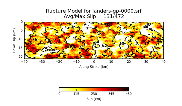
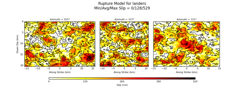
Below are two SRF Plots. The first one represents a plot for the single segment description of Landers. The second plot includes the 3 segments combined into a single plot. Please note the changing azimuth value at the top of each segment.
Seismograms
This is the seismogram for station 4001-
GOF Plots
Below are GOF plots produced by using a single plane versus the 3-segment rupture.


