Difference between revisions of "Community Velocity Models"
m (moved Community Velocity Model to Community Velocity Models: There are more than one community velocity models) |
|||
| Line 39: | Line 39: | ||
== See Also == | == See Also == | ||
| − | |||
*[http://www.scec.org SCEC Home Page] | *[http://www.scec.org SCEC Home Page] | ||
| − | |||
*[[Getting started and Getting Wiki Help]] | *[[Getting started and Getting Wiki Help]] | ||
Revision as of 22:40, 15 February 2016
Community Velocity Models, within SCEC, are computer programs and data files that provide information about earths material properties from the surface to depths below 100km. SCEC's community velocity models (CVM's) provide detailed 3D properties for southern California. Other seismological velocity models are avaiable for other regions. Other CVM's will have capabilities similar to SCEC CVM's. Within SCEC there are two main CVM's, from newest to oldest:
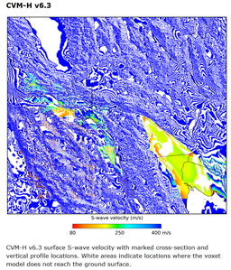
CVM-H
The CVM-H is a velocity model of crust and upper mantle structure in southern California developed by the SCEC community for use in fault systems analysis, strong ground motion prediction, and earthquake hazards assessment. The model describes seismic P- and S-wave velocities and densities, and is comprised of basin structures embedded in tomographic and teleseismic crust and upper mantle models.
This latest release of the CVM-H (6.2) is an important milestone for SCEC, as it represents the integration of various model components, including fully 3D waveform tomographic results. The CVM-H 6.2 consists of basin structures defined using high-quality industry seismic reflection profiles and tens of thousands of direct velocity measurements from boreholes (Plesch et al., 2009; Süss and Shaw, 2003). The basin structures are also compatible with the locations and displacements of major faults represented in the SCEC Community Fault Model (CFM) (Plesch et al., 2007). These basin structures were used to develop travel time tomographic models of the crust (after Hauksson, 2000) extending to a depth of 35 km, and upper mantle teleseismic and surface wave models extending to a depth of 300 km (Prindle and Tanimoto, 2006). These various model components were integrated and used to perform a series of 3D adjoint tomographic inversions that highlight areas of the model that were responsible for mismatches between observed and synthetic waveforms (Tape et al, 2009). Sixteen tomographic iterations, requiring 6800 wavefield simulations, yielded perturbations to the starting model that have been incorporated in the latest model release. CVM-H 6.2 also incorporates a new Moho surface (Yan and Clayton, 2007) and a series of other upgrades to the geotechnical layer (GTL), the Vp-density scaling relationship, and the code that delivers the model.
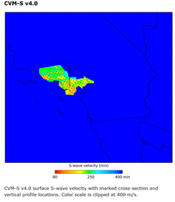
CVM-S
3D Velocity Model for Southern California SCEC Unified Velocity Model
The purpose of the Three-Dimensional Community Velocity Model for Southern California is to provide a unified reference model for the several areas of research that depend of the subsurface velocity structure in their analysis. These include strong motion modeling, seismicity location, and tomographic velocity modeling. It is also hoped that the geologic community will find the basin models useful because they are based on structures and interfaces that are largely derived from geologic structure models. The deeper sediment velocities themselves are obtained from empirical relationships that take into account age of the formation and depth of burial. The coefficients of these relationships are calibrated to sonic logs taken from boreholes in the region. Shallow sediment velocities are taken from geotechnical borehole measurements. Hardrock velocities are based on tomographic studies.
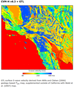
Geotechnical Layer
Surface materials are expected to add scattering and complexity to ground motion seismograms. High resolution maps of surface properties can be combined with geological survey information to create geotechnical layer information about the top 350 meters at sites of interest. CVM models can provide their own GTL (like CVM-S), or external GTL layers can be added on top of lower resolution deep earth structure models (like CVM-H).


